
Road Tunnels Manual
Road Tunnels Manual
This chapter consists of two main subsections:
“Complex Underground Road Networks” has been the subject under consideration by the PIARC Working Group 5 throughout the course of the 2012-2015 cycle.
The working plan consists of two sections:
The terminology “Complex Underground Road Tunnels” covers the following infrastructure:
All the structures share several similar characteristics:
The objective of the case study was to identify structures of this type around the world, to summarise collected information, to analyse it and to establish a number of preliminary recommendations for owners, designers and operators.
While this collection of information is not exhaustive and the summaries do not constitute a scientific database, it nevertheless contains pertinent and interesting findings. The collection of information was limited to the countries of origin of the Working Group 5 members, wherein the working group had active correspondents available to them.
The general methodology has been the following:
At more than 600 pages, a significant volume of information was collected. Therefore a direct publication of all information has been deemed unsuitable. The working group decided to:
Twenty-seven (27) “tunnel complexes” were analysed. The list is provided in §1.7.2.5 below. Several “complexes” consist of two to four tunnels and the actual analysis reflects a total of 41 individual tunnels.
The geographic distribution of structures analysed is shown in the graph below :
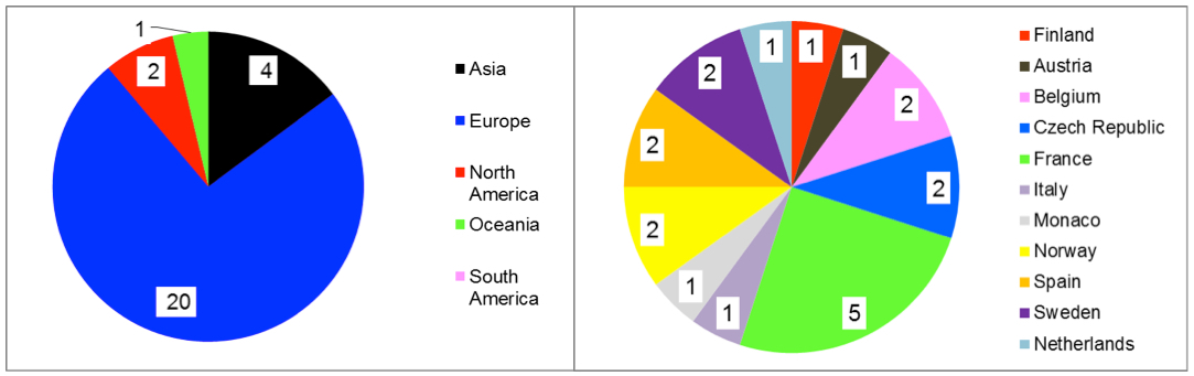
The European tunnels seem over-represented in the sample analysis. This stems,
Particularly, investigations in Chile (Santiago), in Australia (Melbourne and Sydney) and a second project in South Korea were unfortunately unable to be completed by the production date of the current report. They will be the subject of future updates throughout the course of the next cycle during which supplemen-tary analysis from Germany, China, Japan, Singapore and the USA will also be considered.
The key information outlined in the analysis focus on the following aspects:
As the outcome of this analysis, the working group established a number of preliminary recommendations. These recommendations will be the subject of detailed additional developments which will be published in Part B of the report at the end of the 2016-2019 cycle.
These preliminary recommendations, presented in Chapter 11 - Present Situation, Comments and Preliminary Recommendations of the report, deal with the following aspects:
Underground road networks are located mainly in urban areas, and their design (in particular their alignment) has several constraints.
Geometrical conditions which often contribute to traffic incidents, include: meandering curved alignment, insufficient visibility near the access and exit areas, insufficiently defined characteristics of merging or diverging lanes and, poorly designed exit ramp connections towards the surface road network leading to congestion in the main tunnel, etc.
It is recommended that in preparing the alignment, the following be considered:
b - Cross-section
The investigations mentioned above show that 80% of analysed tunnels prohibit the transit of vehicles that weigh over 3.5 tonnes (or 12 tonnes, in some instances). However, the tunnel design does not take into account this restriction, and does not reconsider optimisation of the lane width as well as vertical height clearance.
Investigations carried out on recent projects show that substantial savings (from 20% to 30% depending on the final design characteristics) can be obtained by choosing a reduced vertical height for tunnels that prohibit heavy vehicle usage.
It is recommended that at the earliest stage for developing tunnel projects detailed studies be undertaken to consider and analyse the “function” of the tunnel, traffic conditions (volume and nature of vehicles), as well as the financial feasibility and financing methods. This should be done in such a way as to analyse the advantages of a cross-section with reduced geometric characteristics. This may facilitate the financial optimisation of the project without reducing the level of service or affecting the safety conditions.
c - Ventilation
Underground road networks are usually subjected to large traffic volumes. Traffic congestion is frequent, and the probability of a bottleneck developing within the network is high and recurring. As a result, the ventilation system has to be developed with a detailed analysis of the risks and dangers, taking into account the existence of bottlenecks.
A “pure” longitudinal ventilation system is rarely the appropriate sole response to all the safety requirements, especially in the scenario of a fire located upstream of congested traffic. A longitudinal ventilation system will cause smoke de-stratification downstream of the incident location. This constitutes a danger for any tunnel user blocked or in slow moving downstream traffic.
The addition of smoke extraction gallery or the choice of a transverse or semi-transverse ventilation system is often vital if no other realistic or feasible safety improvement measures can be put into place, and considered as efficient.
It is also necessary to implement equipment allowing the different network branches to operate inde-pendently of each other. This will facilitate the control and the management of smoke propagation during a fire incident.
The risks associated with the traffic of dangerous goods vehicles through a tunnel with a high urban traffic density must be carefully analysed. There are no ventilation systems capable of significantly reducing the effects of a dangerous goods large fire in such traffic conditions.
d - Firefighting
The necessary timeframe for response teams to arrive on site must be subjected to a detailed analysis under normal and peak hour traffic conditions. The objective is to determine whether or not it is necessary to install first line intervention facilities and resources in proximity of the tunnel portals.
The turnover of fire brigade staff is relatively high in urban areas and their interventions in tunnels are rela-tively rare. The high rate of turnover may lead to loss of specialist skills in tunnel intervention. Thus, it is essential to implement tools which allow continuous professional education and training of the teams. A virtual 3D model of the network, associated with simulation software, can provide pertinent, user-friendly and effective tools.
e - Signage
It is fundamental to ensure clear visibility of the exit ramps and a clear legibility of signage, in order to reduce the risk of accidents where exit ramps diverge from the main carriageway.
The locations of interchanges, entry and exit ramps, as well as the concept for signage should be analysed from the conceptual of alignment studies.
f - Environment
In order to reduce atmospheric pollution, communities, stakeholders and residents often demand the installation of filtration devices for in-tunnel air before it is released into the atmosphere.
This results in a decision to install filtration equipment which is rarely rational or technical, but in ad-hoc response to public pressure. Before any decision-making on this issue, it is, however, essential to:
g – Traffic conditions – Traffic management
The connections between exit ramps and the surface network must be equipped in a way which allows supervision and management of traffic in real time. This arrangement allows traffic congestion to be reduced inside the tunnel, and an improvement of safety should tunnel incidents require quick evacuation of users.
The coordination between operators of physically connected infrastructure is in general adequate. However, it is often essential to improve this coordination by clarifying the situation and role of each operator (particularly in the event of traffic congestion and fire incident) by defining common procedures and determining priorities between the different infrastructure parts and their traffic.
Monographs have been established for each of the structures listed in the table below. They are accessible in the Multimedia Kit at the bottom of the page. The monographs of the structures highlighted in amber are in the process of being updated and will be online shortly.
| Continents | Countries | Cities | Names of the tunnels complex | Appendices |
|---|---|---|---|---|
| Asia | China (CHN) | Changsha | Yingpan Tunnel | 1-1 |
| Japan (J) | Tokyo | Chiyoda | 1-2 | |
| Yamate | 1-3 | |||
| South Korea (ROK) | Seoul | Shinlim-Bongchun and Shinlim-2 | 1-4 | |
| Europe | Austria (A) | Vienna | Kaisermühlen | 2-1 |
| Belgium (B) | Brussels | Leopold II | 2-2 | |
| Belliard | 2-3 | |||
| Czech Republic (CZ) | Prague | Blanka Tunnel complex (3 tunnels) | 2-4 | |
| Mrazovka and Strahov | 2-5 | |||
| Finland (FIN) | Helsinki | KEHU - service tunnel | 2-6 | |
| France (F) | Annecy | Courier | 2-7 | |
| Ile-de-France | Duplex A 86 | 2-8 | ||
| Lyon | Croix-Rousse (road tunnel + multimodal tunnel) | 2-9 | ||
| Paris La Défense | A14 / A86 motorway interchange | 2-10 | ||
| Voie des Bâtisseurs | 2-11 | |||
| Italy (I) | Valsassina | Valsassina tunnel | 2-12 | |
| Monaco (MC) | Monaco | Sous le rocher tunnel (2 interconnected tunnels with “Y” form layouts) |
2-13 | |
| Norway (N) | Oslo | Opera tunnel (chain of 4 tunnels) | 2-14 | |
| Tromsø | 3 interconnected tunnels with roundabouts and access to parking lots |
2-15 | ||
| Spain (E) | Madrid | M30 By-pass | 2-16 | |
| M30 Rio | 2-17 | |||
| Sweden (S) | Stockholm | Ring Road – Northern link | 2-18 | |
| Ring Road – Southern link | 2-19 | |||
| The Netherlands (NL) | The Hague | Sijtwendetunnel (chain of 3 tunnels) | 2-20 | |
| North America | Canada / Quebec (CDN) / (QC) | Montreal | Ville-Marie and Viger tunnels | 3-1 |
| USA | Boston | Boston Central Artery | 3-2 | |
| Oceania | Australia (AUS) | Brisbane | M7 Clem Jones Tunnel (CLEM7) | 4-1 |
“Underground Road networks” are “complex systems”. All the recommendations presented in Chapters 1.1 to 1.5 above are applicable to them. Nevertheless, certain “subsets” and “parameters” mentioned in Chapter 1.1 present a much more significant potential impact on underground networks. The “interactions between parameters” (see § 1.1.2.2) are generally and much more extended and complex.
Several major strategic challenges presented in the above chapters, as well as their principal interactions, and the additional parameters below, must be well considered in the process of developing tunnel designs and for the construction and operation of tunnels.
This term is applicable to tunnel cross-section, vertical alignment, implementation of interchanges, access and exit ramps. In addition to the recommendations from § 1.2.1 the following elements should be considered for:
a – Land occupation
Land occupation deals with the surface occupation in open air (roads, buildings and various structures, parks and protected areas, etc.) and the volumetric occupation of the underground space (underground infrastructures such as metro, car parks, various networks, building foundations, etc.)
The interfaces between the underground and surface spaces are numerous: ventilation stacks, access and exit ramps, evacuation corridors and intermediate emergency access.
The underground and surface land occupation constraints are not always compatible with a given location and it is often necessary to decouple surface structures from those underground. This relationship can be implemented through inclined shafts or underground corridors that link any vertical shafts that are located away from the tunnel alignment.
b - Geology, geotechnical, hydrogeology
The geological, geotechnical and hydrogeological conditions have a significant impact on the horizontal and vertical alignment especially with regard to the risk of settlement, the possibility of construction underneath existing structures and any required maintained distances to existing surface or underground struc-tures, in relationship with the construction methodology considered.
These conditions can also influence the position of underground interchanges. For example, in the case of loose soil below groundwater level a localised widening of the cross section to build ramp merge and diverge areas could require construction works starting from the surface (large shafts, treatment and land consolidation works). These works require setting up temporary occupation on the surface. Under such conditions the location of underground interchanges should then also consider the type of land occupation on the surface.
c - Functionality for traffic
The functionality of the alignment mainly deals with areas where connection to the road network at the surface (or possibly with other underground structures) has to be built. The position and the design of the main tunnel portals, the access and exit ramps, as well as the location of interchanges depend on these functionalities.
The location of all these connections is also linked to the volume of traffic in the underground network, as well as its multiple entrances and exits. The connections must take into account the absorption capacity of traffic in the surface road network, adjustments to connections design in order to avoid underground traffic congestion and thus reduce accidents and significant tunnel fire incident risks.
d - Safety – rRsks of accidents
The analysis of existing networks demonstrates a concentration of accidents around areas with curved geometry, overly steep slopes and insufficient visibility around the merge and diverge areas of ramps.
All these elements must be carefully taken into account from the early stage of the design of the horizontal and vertical alignments of a new network.
e - Methods of construction – Time period
The construction methodology has a direct impact on the horizontal and vertical alignments (and vice-versa). They are also strongly guided by the geological, geotechnical and hydrogeological conditions.
The methods of construction can have an important impact on the location of the tunnel portals. In particu-lar, the use of a shield (slurry shield or earth pressure balanced) requires significant site area not only for the assembly of a tunnel-boring machine but also throughout the duration of the works (particularly for the treatment of slurry and provisional storage). A conventionally bored tunnel (when soil conditions permit it) requires fewer facilities close to the portal, and can be accommodated in a smaller site area.
The analysis for the shortening of construction timeframes can have an impact on the horizontal and vertical alignments, for example in order to make possible intermediate construction access sites.
f – Environmental conditions
During operation period of the network, the main concerns are air quality and noise impacts. These concerns have repercussions on the positioning of tunnel portals and ventilation shafts. These issues must be analysed carefully, in particular the ventilation plants as well as the additional equipment likely to reduce the environmental impact.
The position of portals, and the associated temporary work site plants, must also be analysed from an environmental aspect in terms of construction methods and timeframes. For example, a conventional method of construction will have a more significant noise impact as opposed to a TBM construction method. If the tunnel portal is situated in a noise sensitive area, works will have to be suspended during quieter night periods, leading to a prolonged construction period and consequent inflation of costs. A modification of the portal location or changes to the alignment can reduce these impacts.
In addition to the recommendations from § 1.2.2 the following elements should be considered for:
a – Nature of traffic - Function
As mentioned in § 1.7.2.4.b above, the nature of traffic is a factor that must be carefully analysed regarding their initial conditions as well as its evolution over time. Many urban underground networks prohibit heavy vehicles (more than 3.5 t or 12 t depending on different conditions), even though they were designed with standard vertical height clearance and lane width characteristics (defined for the allowance of all types of vehicles).
Analysis of the “function” of the underground network and the evolution of that function is essential. It allows the cross-section to be optimised by choice of geometrical characteristics (vertical height clearance and lane width) to ensure adequacy for the present and future traffic that will use the network.
Savings made regarding construction costs are significant (from 20% to 30% depending on the chosen characteristics). Where applicable, these savings may allow a project to be financed, and thus feasible, where it may not have been with standard vertical clearances and lane width.
b - Volume of traffic
The volume of traffic is the determining factor in defining the number of lanes of the main tunnel, as well as interchange or access and exit ramps.
The volume of traffic should be taken into account when defining the length of merging and diverging lanes for entrances and exits. The risk of congestion, at the connection of exit ramps to the surface network, must also be considered, as well as the consequences that this has on the main tunnel (bottleneck queue) to determine whether or not it is necessary to design and lengthen a parallel lane upstream from the divergence point of the exit ramp from the main road.
c - Ventilation
The ventilation galleries to be installed inside the structure contribute considerably to the spatial requirement. Therefore, it is necessary to proceed to a preliminary “analysis of hazards and risks”, and an initial sizing of ventilation installations before definitively setting the characteristics of the functional cross-section. This approach is often iterative.
d – Geology - Geotechnics - Hydrogeology - Methods of construction
The geological, hydrogeological and geotechnical conditions, as well as methods of construction (which are often interlinked) have a vital impact on the shape and surface area of the cross-section. The following example illustrates this interaction.
In loose soil below groundwater level, the use of a shield will be required for the construction of the main tunnel. The main tunnel will be circular in shape. However, the cross-section will also depend on other functions:
Recommendations in section 1.2.3 are integrally applicable to “underground road networks”. The analysis approach must, nevertheless, take into account the complexity of underground networks and the aggravating influence of certain factors, in particular:
a - Traffic
The volume of traffic is generally more significant and in high traffic volume conditions traffic congestion is much more frequent. It follows that the number of persons in tunnel is much higher and in the event of an incident, the number of users to evacuate will be more significant.
Ramps merge and diverge areas are important locations in terms of risk of accidents.
The assumption, which is sometimes prevalent from the start of projects, that there will never be a traffic blockage must be analysed with much circumspection. It is indeed possible to regulate the volume of traffic entering into an underground network in order to eliminate all risk of bottlenecks. Nevertheless, this leads to a significant decrease in the capacity of the infrastructure (in terms of traffic volume) which often goes against the reasoning that justifies its construction. Over time, measures of reducing entering traffic must be relaxed, or even abandoned because of the need to increase traffic capacity. The probability and recurrence of bottlenecks increase, disregarding the initial assumption upon which the network was based (particularly in terms of safety and ventilation during incidents).
b - Emergency evacuation – emergency access
The analysis must take into account:
c - Ventilation
The concept and design of ventilation systems must take into account:
d – Communication with users
Communication with tunnel users must be reinforced and adapted throughout the multitude of branches within the network. Communication must be able to be differentiated between the different branches according to operational needs, especially in the case of fires.
Users must be able to identify their position inside the network, which would require, for example, the installation of specific signs, colour codes, etc.
Directional signs and prior information signs at interchanges or ramps must be subjected to careful consideration, particularly the visibility distances with regards to signals and the clear legibility of the signage.
e – Operational needs
Specific operational needs (cf. § 1.2.3.6) must be adapted to the complexity of a network, to the volume of traffic and to the resulting increased difficulties of achieving interventions under traffic conditions.
Recommendations in section 1.2.4 are also applicable to “underground road networks”. Nevertheless, anal-yses must take into account the complexities of underground road networks and the supplementary needs or conditions mentioned in Chapter 1.7.3.
The interfaces between operators of associated or related network must be subjected to a specific analysis, particularly for all aspects concerning, on the one hand, traffic management and, on the other hand, safety (especially fire incidents), including evacuation of users and intervention of emergency response agencies in response to fire incidents.
Control centres must take account of the interfaces within the network and between diverse operators. They must allow the transmission of common information which is essential to each operator, and facilitate the possible temporary hierarchy of one control centre over another. The architectural design of the network of control centres, and of their performance and methods, must be subjected to an overall analysis of organisa-tions, responsibilities, challenges and risks. This analysis should reflect a range of operational conditions such as during normal and emergency scenarios, and should review the interaction between the different subsections of the network and the respective responsibilities of each control centre.